electrical theory and electrical fundementals for all electrical related people . students , engineers, electrician #electricaltheorems,electrical,

Thursday, 11 December 2014

itemprop='blogPost' itemscope='itemscope' itemtype='http://schema.org/BlogPosting'>

DIODE

electrical theory and electrical fundementals for all electrical related people . students , engineers, electrician #electricaltheorems,electrical,


A diode generally refers to a two-terminal solid-state semiconductor device that presents a low impedance to current flow in one direction and a high impedance to current flow in the opposite direction. These properties allow the diode to be used as a one-way current valve in electronic circuits. Rectifiers are a class of circuits whose purpose is to convert ac waveforms (usually sinusoidal and with zero average value) into a waveform that has a significant non-zero average value (dc component). Simply stated, rectifiers are ac-to-dc energy converter circuits. Most rectifier circuits employ diodes as the principal elements in the energy conversion process; thus the almost inseparable notions of diodes and rectifiers. The general electrical characteristics of common diodes and some simple rectifier topologies incorporating diodes are discussed.
Most diodes are made from a host crystal of silicon (Si) with appropriate impurity elements introduced to modify, in a controlled manner, the electrical characteristics of the device. These diodes are the typical pn-junction (or bipolar) devices used in electronic circuits. Another type is the Schottky diode (unipolar), produced by placing a metal layer directly onto the semiconductor [Schottky, 1938; Mott, 1938]. The metal semiconductor interface serves the same function as the pn semiconductor materials such as gallium-arsenide (GaAs) and silicon-carbide (SiC) are also in use for new and specialized applications of diodes. Detailed discussion of diode structures and the physics of their operation can be found in later paragraphs of this section. The electrical circuit symbol for a bipolar diode is shown in Fig.1. The polarities associated with the forward voltage drop for forward current flow are also included. Current or voltage opposite to the polarities indicated are considered to be negative values with respect to the diode conventions shown.

The characteristic curve shown in Fig.2 is representative of the currentvoltage dependencies of typical diodes. The diode conducts forward current with a small forward voltage drop across the device, simulating a closed switch. The relationship between the forward current and forward voltage is approximately given by the Shockley diode equation [Shockley, 1949]:
where
Fig 2
Is is the leakage current through the diode, q is the electronic charge, n is a correction factor, k is Boltzmann’s constant, and T is the temperature of the semiconductor. Around the knee of the curve in Fig.2 is a positive voltage that is termed the turn-on or sometimes the threshold voltage for the diode. This value is an approximate voltage above which the diode is considered turned “on” and can be modeled to first degree as a closed switch with constant forward drop. Below the threshold voltage value the diode is considered weakly conducting and approximated as an open switch. The exponential relationship means that the diode forward current can change by orders of magnitude before there is a large change in diode voltage, thus providing the simple circuit model during conduction. The nonlinear relationship also provides a means of frequency mixing for applications in modulation circuits. Reverse voltage applied to the diode causes a small leakage current (negative according to the sign convention) to flow that is typically orders of magnitude lower than current in the forward direction. The diode can withstand reverse voltages up to a limit determined by its physical construction and the semiconductor material used. Beyond this value the reverse voltage imparts enough energy to the charge carriers to cause large increases in current. The mechanisms by which this current increase occurs are impact ionization (avalanche) [McKay, 954] and a tunneling phenomenon (Zener breakdown) [Moll, 1964]. Avalanche breakdown results in large1power dissipation in the diode, is generally destructive, and should be avoided at all times. Both breakdown regions are superimposed in Fig .2 for comparison of their effects on the shape of the diode characteristic curve. Avalanche breakdown occurs for reverse applied voltages in the range of volts to kilovolts depending on the exact design of the diode. Zener breakdown occurs at much lower voltages than the avalanche mechanism. Diodes specifically designed to operate in the Zener breakdown mode are used extensively as voltage regulators in regulator integrated circuits and as discrete components in large regulated power supplies. During forward conduction the power loss in the diode can become excessive for large current flow. Schottky diodes have an inherently lower turn-on voltage than pn -junction diodes and are therefore more desirable in applications where the energy losses in the diodes are significant (such as output rectifiers in switching power supplies). Other considerations such as recovery characteristics from forward conduction to reverse blocking

Saturday, 6 December 2014

itemprop='blogPost' itemscope='itemscope' itemtype='http://schema.org/BlogPosting'>

SPEED CONTROL OF INDUCTION MACHINE

electrical theory and electrical fundementals for all electrical related people . students , engineers, electrician #electricaltheorems,electrical,


We have seen the speed torque characteristic of the machine. In the stable region of operation in the motoring mode, the curve is rather steep and goes from zero torque at synchronous speed to the stall torque at a value of slip s = ŝ. Normally ŝ may be such that stall torque is about three times that of the rated operating torque of the machine, and hence may be about 0.3 or less.  This means that in the entire loading range of the machine, the speed change is quite small.  The machine speed is quite stiff with respect to load changes.  The entire speed variation is only in the range ns  to (1 − ŝ)ns, ns  being dependent on supply frequency and number of poles.

The foregoing discussion shows that the induction machine, when operating from mains is essentially a constant speed machine.  Many industrial drives, typically for fan or pump applications, have typically constant speed requirements and hence the induction machine is ideally suited for these. However,the induction machine, especially the squirrel cage type, is quite rugged and has a simple construction.  Therefore it is good candidate for variable speed applications if it can be achieved.

Speed control by changing applied voltage

From the torque equation of the induction machine given  we can see that the torque depends on the square of the applied voltage. The variation of speed torque curves with respect to the applied voltage is shown in fig. These curves show that the slip at maximum torque ŝ remains same, while the value of stall torque comes down with decrease in applied voltage. The speed range for stable operation remains the same.
 Further, we also note that the starting torque is also lower at lower voltages. Thus, even if a given voltage level is sufficient for achieving the running torque, the machine may not start. This method of trying to control the speed is best suited for loads that require very little starting torque, but their torque requirement may increase with speed. also shows a load torque characteristic — one that is typical of a fan type of load. In a fan (blower) type of load,the variation of torque with speed is such that T ω2. Here one can see that it may be possible to run the motor to lower speeds within the range ns  to (1 − ŝ)ns. Further, since the load torque at zero speed is zero, the machine can start even at reduced voltages. This will not be possible with constant torque type of loads. One may note that if the applied voltage is reduced, the voltage across the magnetising branch also comes down. This in turn means that the magnetizing current and hence flux level are reduced.  Reduction in the flux level in the machine impairs torque production(recall explantions on torque production), which is primarily the explanation. If, however, the machine is running under lightly loaded conditions, then operating under rated flux levels is not required. Under such conditions, reduction in magnetizingcurrent improves the power factor of operation. Some amount of energy saving may also be achieved.
Voltage control may be achieved by adding series resistors (a lossy, inefficient proposition), or a series inductor / autotransformer (a bulky solution) or a more modern solution using semiconductor devices. A typical solid state circuit used for this purpose is the AC voltage controller or AC chopper. Another use of voltage control is in the so-called ‘soft-start’ of the machine. This is discussed in the section on starting methods.

Rotor resistance control

The reader may recall from eqn.17 the expression for the torque of the induction machine. Clearly, it is dependent on the rotor resistance.  Further, shows that the maximum value is independent of the rotor resistance. The slip at maximum torque is dependent on the rotor resistance. Therefore, we may expect that if the rotor resistance is changed, the maximum torque point shifts to higher slip values, while retaining a constant torque. a family of torque-speed characteristic obtained by changing the rotor resistance.


 Note that while the maximum torque and synchronous speed remain constant, the slip at which maximum torque occurs increases with increase in rotor resistance, and so does the starting torque. whether the load is of constant torque type or fan-type, it is evident that the speed control range is more with this method.  Further, rotor resistance control could also be used as a means of generating high starting torque.
For all its advantages, the scheme has two serious drawbacks.  Firstly, in order to vary the rotor resistance, it is necessary to connect external variable resistors (winding resistance itself cannot be changed).  This, therefore necessitates a slip-ring machine, since only in that case rotor terminals are available outside. For cage rotor machines, there are no rotor terminals.  Secondly, the method is not very efficient since the additional resistance and operation at high slips entails dissipation. The resistors connected to the slip-ring brushes should have good power dissipation capability. Water based rheostats may be used for this. A ‘solid-state’ alternative to a rheostat is a chopper controlled resistance where the duty ratio control of of the chopper presents a variable resistance load to the rotor of the induction machine.

Stator frequency control

The expression for the synchronous speed indicates that by changing the stator frequency also it can be changed. This can be achieved by using power electronic circuits called inverters which convert dc to ac of desired frequency. Depending on the type of control scheme of the inverter, the ac generated may be variable-frequency-fixed-amplitude or variable-frequency- variable-amplitude type. Power electronic control achieves smooth variation of voltage and frequency of the ac output. This when fed to the machine is capable of running at a controlled speed. However, consider the equation for the induced emf in the induction machine.
                                               V =4.44Nφmf
where N is the number of the turns per phase, φm is the peak flux in the air gap and f is the frequency. Note that in order to reduce the speed, frequency has to be reduced. If the frequency is reduced while the voltage is kept constant, thereby requiring the amplitude of induced emf to remain the same, flux has to increase. This is not advisable since the machine likely to enter deep saturation. If this is to be avoided, then flux level must be maintained constant which implies that voltage must be reduced along with frequency. The ratio is held constant in order to maintain the flux level for maximum torque capability. Actually, it is the voltage across the magnetizing branch of the exact equivalent circuit that must be maintained constant, for it is that which determines the induced emf. Under conditions where the stator voltage drop is negligible compared the applied voltage,
In this mode of operation, the voltage across the magnetizing inductance in the ’exact’ equivalent circuit reduces in amplitude with reduction in frequency and so does the inductive reactance. This implies that the current through the inductance and the flux in the machine remains constant.  The speed torque characteristics at any frequency may be estimated as before. There is one curve for every excitation frequency considered corresponding to every value of synchronous speed. The curves are shown below. It may be seen that the maximum torque remains constant.

Tuesday, 2 December 2014

itemprop='blogPost' itemscope='itemscope' itemtype='http://schema.org/BlogPosting'>

BATTERY

electrical theory and electrical fundementals for all electrical related people . students , engineers, electrician #electricaltheorems,electrical,

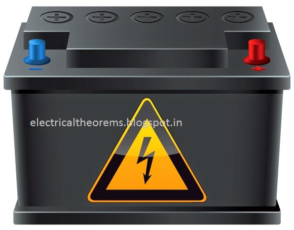
Batteries operate by converting chemical energy into electrical energy through electrochemical discharge reactions. Batteries are composed of one or more cells, each containing a positive electrode, negative electrode, separator, and electrolyte. Cells can be divided into two major classes: primary and secondary

Primary cells are not rechargeable and must be replaced once the reactants are depleted. Secondary cells are rechargeable and require a DC charging source to restore reactants to their fully charged state. Examples of primary cells include carbon-zinc (Leclanche or dry cell), alkaline-manganese, mercuryzinc, silver-zinc, and lithium cells (e.g., lithium-manganese dioxide, lithium-sulfur dioxide, and lithiumthionyl chloride). Examples of secondary cells include lead-lead dioxide (lead-acid), nickel-cadmium, nickel-iron, nickel-hydrogen, nickel-metal hydride, silver-zinc, silver-cadmium, and lithium-ion. For aircraft applications, secondary cells are the most prominent, but primary cells are sometimes used for powering critical avionics equipment (e.g., flight data recorders).

Batteries 

are rated in terms of their nominal voltage and ampere-hour capacity. The voltage rating is based on the number of cells connected in series and the nominal voltage of each cell (2.0 V for leadacid and 1.2 V for nickel-cadmium). The most common voltage rating for aircraft batteries is 24 V. A24-V lead-acid battery contains 12 cells, while a 24-V nickel-cadmium battery contains either 19 or 20 cells (the U.S. military rates 19-cell batteries at 24 V). Voltage ratings of 22.8, 25.2, and 26.4 V are also common with nickel-cadmium batteries, consisting of 19, 20, or 22 cells, respectively. Twelve-volt lead-acid batteries, consisting of six cells in series, are also used in many general aviation aircraft. The ampere-hour (Ah) capacity available from a fully charged battery depends on its temperature, rate of discharge, and age. Normally, aircraft batteries are rated at room temperature (25°C), the C-rate(1-hour rate), and beginning of life. Military batteries, however, often are rated in terms of the end- oflife capacity, i.e., the minimum capacity before the battery is considered unserviceable. Capacity ratings of aircraft batteries vary widely, generally ranging from 3 to 65 Ah.
The maximum power available from a battery depends on its internal construction. High rate cells, for example, are designed specifically to have very low internal impedance as required for starting turbine engines and auxiliary power units (APUs). Unfortunately, no universally accepted standard exists for defining the peak power capability of an aircraft battery. For lead-acid batteries, the peak power typically is defined in terms of the cold-cranking amperes, or CCA rating. For nickel-cadmium batteries, the peak power rating typically is defined in terms of the current at maximum power, or Imp rating. These ratings are based on different temperatures (18°C for CCA, 23°C for Imp), making it difficult to compare different battery types. Furthermore, neither rating adequately characterizes the battery’s initial peak current capability, which is especially important for engine start applications. More rigorous peak power specifications have been included in some military standards. For example, MIL-B-8565/15 specifies the initial peak current, the current after 15 s, and the capacity after 60 s, during a 14-V constant voltage discharge at two different temperatures (24 and26°C). The state-of-charge of a battery is the percentage of its capacity available relative to the capacity when it is fully charged. By this definition, a fully charged battery has a state-of-charge of 100% and a battery with 20% of its capacity removed has a state-of-charge of 80%. The state-of-health of a battery is the percentage of its capacity available when fully charged relative to its rated capacity. For example, a battery rated at 30 Ah, but only capable of delivering 24 Ah when fully charged, will have a state-of-health of24/30 10080%. Thus, the state-of-health takes into account the loss of capacity as the battery ages

Lead-Acid Batteries

Theory of Operation

The chemical reactions that occur in a lead-acid battery are represented by the following equations:
As the cell is charged, the sulfuric acid (H2 SO4) concentration increases and becomes highest when the cell is fully charged. Likewise, when the cell is discharged, the acid concentration decreases and becomes most dilute when the cell is fully discharged. The acid concentration generally is expressed in terms of specific gravity, which is weight of the electrolyte compared to the weight of an equal volume of pure water.
The cell’s specific gravity can be estimated from its open circuit voltage using the following equation:

Specific Gravity (SG)= Open Circuit Voltage (OCV)- 0.84

There are two basic cell types: vented and recombinant. Vented cells have a flooded electrolyte, and the hydrogen and oxygen gases generated during charging are vented from the cell container. Recombinant cells have a starved or gelled electrolyte, and the oxygen generated from the positive electrode during charging diffuses to the negative electrode where it recombines to form water by the following reaction:

Pb + H2SO4 + 1/2O → PbSO4 + H2O

The recombination reaction suppresses hydrogen evolution at the negative electrode, thereby allowing the cell to be sealed. In practice, the recombination efficiency is not 100% and a resealable valve regulates the internal pressure at a relatively low value, generally below 10 psig. For this reason, sealed lead-acid cells are often called “valve-regulated lead-acid” (VRLA) cells.

Nickel-Cadmium Batteries

Theory of Operation

The chemical reactions that occur in a nickel-cadmium battery are represented by the following equations:

There are two basic cell types: vented and recombinant. Vented cells have a flooded electrolyte, and the hydrogen and oxygen gases generated during charging are vented from the cell container. Recombinant cells have a starved electrolyte, and the oxygen generated from the positive electrode during charging diffuses to the negative electrode where it recombines to form cadmium hydroxide by the following reaction:
Cd + H2O + 1/2O→ Cd(OH)
The recombination reaction suppresses hydrogen evolution at the negative electrode, thereby allowing the cell to be sealed. Unlike valve-regulated lead-acid cells, recombinant nickel-cadmium cells are sealed with a high-pressure vent that releases only during abusive conditions. Thus, these cells remain sealed under normal charging conditions. However, provisions for gas escape must still be provided when designing battery cases since abnormal conditions may be encountered periodically (e.g., in the event of a charger failure that causes an overcurrent condition).

Tuesday, 25 November 2014

itemprop='blogPost' itemscope='itemscope' itemtype='http://schema.org/BlogPosting'>

ELECTRIC CURRENT

electrical theory and electrical fundementals for all electrical related people . students , engineers, electrician #electricaltheorems,electrical,


An electric current can be broadly defined as charged particles in motion - a flow of charge. The most obvious effect of a current would seem to be the transfer of charge from one place to another. So it is, when a charged body is discharged by touching it with an earthed wire, or when lightning strikes a tree. However, it is important to realise that most currents flow in closed loops or circuits with no net transfer of charge. When there is a steady current the distribution of charge around a circuit remains constant and every part of the circuit remains substantially neutral.

The effects of electric current 

You can't see anything move in an electric current but currents do have a number of extremely important effects, which can be broadly classified as shown in the first column of table 3.1. This list is by no means exhaustive. Some of the topics are discussed in later chapters. In this chapter we are concerned in general terms with the charge, mass and energy transferred by a current

The measurement of electric current


Electric current is measured by means of a device which responds quantitatively to one or other of the effects of the current. Because current is a flow of charge, the device usually has to be connected so that the current goes through it.
Each system has advantages and disadvantages. The choice is determined by the exigencies of the situation. For example a clip-on ammeter does not require the interruption of the current, but it is bulky and not very sensitive. By contrast a digital ammeter responds quickly. Moving coil meters have the advantage of simplicity and long-term stability.

Movement of charge

Any movement of charge constitutes an electric current. The charge carriers could be electrons in a vacuum, electrons in a metal, 'holes' in a semiconductor or ions in a solution. The charge may move in free space, through a conductor or on a conveyor belt. An obvious manifestation of charge movement is an electric spark. At each spark some charge is transferred. Together a sequence of sparks makes up an intermittent current in which each spark contributes a current pulse. If the spark gap is narrowed so that the sparks become more frequent, they tend to merge to make a continuous current. 

Definition and unit of current 

The value of a current in a wire at any point is defined to be equal to the rate of flow of net positive charge past that point. The direction of the current is defined to be the direction of flow of positive charge.
            If the charge carriers are actually negative then the direction of the current is opposite to the flow direction of the particles. Thus a current of one ampere to the right could be either positive charge flowing to the right at 1 coulomb per second or negative charge flowing to the left at 1 coulomb per second, or some combination of flows in both directions such 0.5 C.s-1 each way.
The SI unit of electric current is the ampere (symbol A), equal to one coulomb per second. Because current is easier to measure than charge, the physical standards have been established using current as the base quantity, so the coulomb is defined as an ampere-second (A.s). The ampere is defined in terms of magnetic effects 

Current 

When there is an electric current in a circuit, energy is generally being transferred from a source to a load: energy is transferred from a battery to a lamp or from a nerve cell to measuring electrodes. In such circuits, the current is associated with the energy transfer.