electrical theory and electrical fundementals for all electrical related people . students , engineers, electrician #electricaltheorems,electrical,

Tuesday, 2 December 2014

itemprop='blogPost' itemscope='itemscope' itemtype='http://schema.org/BlogPosting'>

BATTERY

electrical theory and electrical fundementals for all electrical related people . students , engineers, electrician #electricaltheorems,electrical,

Batteries operate by converting chemical energy into electrical energy through electrochemical discharge reactions. Batteries are composed of one or more cells, each containing a positive electrode, negative electrode, separator, and electrolyte. Cells can be divided into two major classes: primary and secondary
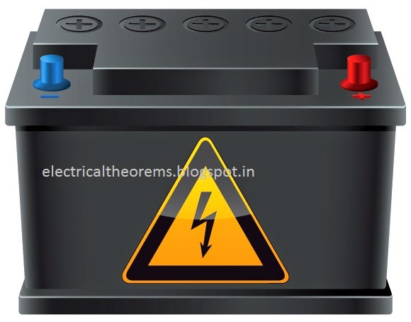
Primary cells are not rechargeable and must be replaced once the reactants are depleted. Secondary cells are rechargeable and require a DC charging source to restore reactants to their fully charged state. Examples of primary cells include carbon-zinc (Leclanche or dry cell), alkaline-manganese, mercuryzinc, silver-zinc, and lithium cells (e.g., lithium-manganese dioxide, lithium-sulfur dioxide, and lithiumthionyl chloride). Examples of secondary cells include lead-lead dioxide (lead-acid), nickel-cadmium, nickel-iron, nickel-hydrogen, nickel-metal hydride, silver-zinc, silver-cadmium, and lithium-ion. For aircraft applications, secondary cells are the most prominent, but primary cells are sometimes used for powering critical avionics equipment (e.g., flight data recorders).

Batteries 

are rated in terms of their nominal voltage and ampere-hour capacity. The voltage rating is based on the number of cells connected in series and the nominal voltage of each cell (2.0 V for leadacid and 1.2 V for nickel-cadmium). The most common voltage rating for aircraft batteries is 24 V. A24-V lead-acid battery contains 12 cells, while a 24-V nickel-cadmium battery contains either 19 or 20 cells (the U.S. military rates 19-cell batteries at 24 V). Voltage ratings of 22.8, 25.2, and 26.4 V are also common with nickel-cadmium batteries, consisting of 19, 20, or 22 cells, respectively. Twelve-volt lead-acid batteries, consisting of six cells in series, are also used in many general aviation aircraft. The ampere-hour (Ah) capacity available from a fully charged battery depends on its temperature, rate of discharge, and age. Normally, aircraft batteries are rated at room temperature (25°C), the C-rate(1-hour rate), and beginning of life. Military batteries, however, often are rated in terms of the end- oflife capacity, i.e., the minimum capacity before the battery is considered unserviceable. Capacity ratings of aircraft batteries vary widely, generally ranging from 3 to 65 Ah.
The maximum power available from a battery depends on its internal construction. High rate cells, for example, are designed specifically to have very low internal impedance as required for starting turbine engines and auxiliary power units (APUs). Unfortunately, no universally accepted standard exists for defining the peak power capability of an aircraft battery. For lead-acid batteries, the peak power typically is defined in terms of the cold-cranking amperes, or CCA rating. For nickel-cadmium batteries, the peak power rating typically is defined in terms of the current at maximum power, or Imp rating. These ratings are based on different temperatures (18°C for CCA, 23°C for Imp), making it difficult to compare different battery types. Furthermore, neither rating adequately characterizes the battery’s initial peak current capability, which is especially important for engine start applications. More rigorous peak power specifications have been included in some military standards. For example, MIL-B-8565/15 specifies the initial peak current, the current after 15 s, and the capacity after 60 s, during a 14-V constant voltage discharge at two different temperatures (24 and26°C). The state-of-charge of a battery is the percentage of its capacity available relative to the capacity when it is fully charged. By this definition, a fully charged battery has a state-of-charge of 100% and a battery with 20% of its capacity removed has a state-of-charge of 80%. The state-of-health of a battery is the percentage of its capacity available when fully charged relative to its rated capacity. For example, a battery rated at 30 Ah, but only capable of delivering 24 Ah when fully charged, will have a state-of-health of24/30 10080%. Thus, the state-of-health takes into account the loss of capacity as the battery ages

Lead-Acid Batteries

Theory of Operation

The chemical reactions that occur in a lead-acid battery are represented by the following equations:
As the cell is charged, the sulfuric acid (H2 SO4) concentration increases and becomes highest when the cell is fully charged. Likewise, when the cell is discharged, the acid concentration decreases and becomes most dilute when the cell is fully discharged. The acid concentration generally is expressed in terms of specific gravity, which is weight of the electrolyte compared to the weight of an equal volume of pure water.
The cell’s specific gravity can be estimated from its open circuit voltage using the following equation:

Specific Gravity (SG)= Open Circuit Voltage (OCV)- 0.84

There are two basic cell types: vented and recombinant. Vented cells have a flooded electrolyte, and the hydrogen and oxygen gases generated during charging are vented from the cell container. Recombinant cells have a starved or gelled electrolyte, and the oxygen generated from the positive electrode during charging diffuses to the negative electrode where it recombines to form water by the following reaction:

Pb + H2SO4 + 1/2O → PbSO4 + H2O

The recombination reaction suppresses hydrogen evolution at the negative electrode, thereby allowing the cell to be sealed. In practice, the recombination efficiency is not 100% and a resealable valve regulates the internal pressure at a relatively low value, generally below 10 psig. For this reason, sealed lead-acid cells are often called “valve-regulated lead-acid” (VRLA) cells.

Nickel-Cadmium Batteries

Theory of Operation

The chemical reactions that occur in a nickel-cadmium battery are represented by the following equations:

There are two basic cell types: vented and recombinant. Vented cells have a flooded electrolyte, and the hydrogen and oxygen gases generated during charging are vented from the cell container. Recombinant cells have a starved electrolyte, and the oxygen generated from the positive electrode during charging diffuses to the negative electrode where it recombines to form cadmium hydroxide by the following reaction:
Cd + H2O + 1/2O→ Cd(OH)
The recombination reaction suppresses hydrogen evolution at the negative electrode, thereby allowing the cell to be sealed. Unlike valve-regulated lead-acid cells, recombinant nickel-cadmium cells are sealed with a high-pressure vent that releases only during abusive conditions. Thus, these cells remain sealed under normal charging conditions. However, provisions for gas escape must still be provided when designing battery cases since abnormal conditions may be encountered periodically (e.g., in the event of a charger failure that causes an overcurrent condition).

Tuesday, 25 November 2014

itemprop='blogPost' itemscope='itemscope' itemtype='http://schema.org/BlogPosting'>

ELECTRIC CURRENT

electrical theory and electrical fundementals for all electrical related people . students , engineers, electrician #electricaltheorems,electrical,


An electric current can be broadly defined as charged particles in motion - a flow of charge. The most obvious effect of a current would seem to be the transfer of charge from one place to another. So it is, when a charged body is discharged by touching it with an earthed wire, or when lightning strikes a tree. However, it is important to realise that most currents flow in closed loops or circuits with no net transfer of charge. When there is a steady current the distribution of charge around a circuit remains constant and every part of the circuit remains substantially neutral.

The effects of electric current 

You can't see anything move in an electric current but currents do have a number of extremely important effects, which can be broadly classified as shown in the first column of table 3.1. This list is by no means exhaustive. Some of the topics are discussed in later chapters. In this chapter we are concerned in general terms with the charge, mass and energy transferred by a current

The measurement of electric current


Electric current is measured by means of a device which responds quantitatively to one or other of the effects of the current. Because current is a flow of charge, the device usually has to be connected so that the current goes through it.
Each system has advantages and disadvantages. The choice is determined by the exigencies of the situation. For example a clip-on ammeter does not require the interruption of the current, but it is bulky and not very sensitive. By contrast a digital ammeter responds quickly. Moving coil meters have the advantage of simplicity and long-term stability.

Movement of charge

Any movement of charge constitutes an electric current. The charge carriers could be electrons in a vacuum, electrons in a metal, 'holes' in a semiconductor or ions in a solution. The charge may move in free space, through a conductor or on a conveyor belt. An obvious manifestation of charge movement is an electric spark. At each spark some charge is transferred. Together a sequence of sparks makes up an intermittent current in which each spark contributes a current pulse. If the spark gap is narrowed so that the sparks become more frequent, they tend to merge to make a continuous current. 

Definition and unit of current 

The value of a current in a wire at any point is defined to be equal to the rate of flow of net positive charge past that point. The direction of the current is defined to be the direction of flow of positive charge.
            If the charge carriers are actually negative then the direction of the current is opposite to the flow direction of the particles. Thus a current of one ampere to the right could be either positive charge flowing to the right at 1 coulomb per second or negative charge flowing to the left at 1 coulomb per second, or some combination of flows in both directions such 0.5 C.s-1 each way.
The SI unit of electric current is the ampere (symbol A), equal to one coulomb per second. Because current is easier to measure than charge, the physical standards have been established using current as the base quantity, so the coulomb is defined as an ampere-second (A.s). The ampere is defined in terms of magnetic effects 

Current 

When there is an electric current in a circuit, energy is generally being transferred from a source to a load: energy is transferred from a battery to a lamp or from a nerve cell to measuring electrodes. In such circuits, the current is associated with the energy transfer.

Monday, 24 November 2014

itemprop='blogPost' itemscope='itemscope' itemtype='http://schema.org/BlogPosting'>

SPEED CONTROL OF DC SERIES MOTOR

electrical theory and electrical fundementals for all electrical related people . students , engineers, electrician #electricaltheorems,electrical,

Speed Control of Series Motors

1. Flux Control Method: 

: Variations in the flux of a series motor can be brought about in any one of the following ways:

 (a) Field Diverters:

 The series winding are shunted by a variable resistance known as field diverter. Any desired amount of current can be passed through the diverter by adjusting its resistance. Hence the flux can be decreased and consequently, the speed of the motor increased.

 (b) Armature Diverter:

A diverter across the armature can be used for giving speeds lower than the normal speed. For a given constant load torque, if Ia is reduced due to armature diverter, the  must increase (TaIa ) This results in an increase in current taken from the supply(which increases the flux and a fall in speed (N  I/ )). The variation in speed can be controlled by varying the diverter resistance.


(c) Trapped Field Control Field: This method is often used in electric traction. The number of series filed turns in the circuit can be changed. With full field, the motor runs at its minimum speed which can be raised in steps by cutting out some of the series turns.
 (d) Paralleling Field coils: this method used for fan motors, several speeds can be obtained by regrouping the field coils. It is seen that for a4-pole motor, three speeds can be obtained easily.


 Variable Resistance in Series with Motor


By increasing the resistance in series with the armature the voltage applied across the armature terminals can be decreased. With reduced voltage across the armature, the speed is reduced. However, it will be noted that since full motor current passes through this resistance, there is a considerable loss of power in it.

Sunday, 23 November 2014

itemprop='blogPost' itemscope='itemscope' itemtype='http://schema.org/BlogPosting'>

LIGHT EMITTING DIODE (LED)

electrical theory and electrical fundementals for all electrical related people . students , engineers, electrician #electricaltheorems,electrical,


To explain the theory and the underlying principle behind the functioning of an LED
The first known report of a light-emitting solid-state diode was made in 1907 by
the British experimenter H. J. Round. In the mid 1920s, Russian Oleg Vladimirovich Losev independently created the first LED, although his research was ignored at that time.
• In 1955, Rubin Braunstein of the Radio Corporation of America reported on infrared emission from gallium arsenide (GaAs) and other semiconductor alloys.
• Experimenters at Texas Instruments, Bob Biard and Gary Pittman, found in 1961 that gallium arsenide gave off infrared radiation when electric current was applied. Biard & Pittman received the patent for the infrared light-emitting diode.

• In 1962, Nick Holonyak Jr., of the General Electric Company and later with the University of Illinois at Urbana-Champaign, developed the first practical visible spectrum LED. He is seen as the "father of the light-emitting diode".
• In 1972, M. George Craford, Holonyak's former graduate student, invented the first yellow LED and 10x brighter red and red-orange LEDs.
• Shuji  Nakamura of Nichia Corporation of Japan demonstrated the first high brightness blue LED based on In GaN. The 2006 Millennium Technology Prize was awarded to Nakamura for his invention.

THEORY

A Light emitting diode (LED) is essentially a pn junction diode. When carriers are injected across a forward-biased junction, it emits incoherent light. Most of the commercial LEDs are realized using a highly doped n and a p Junction.
To understand the principle, let’s consider an unbiased pn+ junction band . The depletion region extends mainly into the p-side. There is a potential barrier from Ec on the n-side to the Ec on the p-side, called the built-in voltage, V0. This potential barrier prevents the excess free electrons on the n+ side from diffusing into the p side.
When a Voltage V is applied across the junction, the built-in potential is reduced from V0 to V0 – V. This allows the electrons from the n+ side to get injected into the p-side. Since electrons are the minority carriers in the p-side, this process is called minority carrier injection. But the hole injection from the p side to n+ side is very less and so the current is primarily due to the flow of electrons into the p-side. Appendix 1) results in spontaneous emission of photons (light). This effect is called injection electroluminescence. These photons should be allowed to escape from the device without being reabsorbed.
The recombination can be classified into the following two kinds


• Direct recombination

• Indirect recombination

Direct Recombination:

In direct band gap materials, the minimum energy of the conduction band lies directly above the maximum energy of the valence band in momentum space energy 

. In this material, free electrons at the bottom of the conduction band can recombine directly with free holes at the top of the valence band, as the momentum of the two particles is the same. This transition from conduction band to valence band involves photon emission (takes care of the principle of energy conservation). This is known as direct recombination. Direct recombination occurs spontaneously. GaAs is an example of a direct band-gap material.

Indirect Recombination

In the indirect band gap materials, the minimum energy in the conduction band is shifted by a k-vector relative to the valence band. The k-vector difference represents a difference in momentum. Due to this difference in momentum, the probability of direct electronhole recombination is less. In these materials, additional dopants(impurities) are added which form very shallow donor states. These donor states capture the free electrons locally; provides the necessary momentum shift for recombination. These donor states serve as the recombination centers. This is called Indirect (non-radiative) Recombination.

 E-k plot of an indirect band gap material and an example of how Nitrogen serves as a recombination center in GaAsP. In this case it creates a donor state, when SiC is doped with Al, it recombination takes place through an acceptor level. The indirect recombination should satisfy both conservation energy, and momentum. Thus besides a photon emission, phononemission or absorption has to take place. GaP is an example of an indirect band-gap material.
The wavelength of the light emitted, and hence the color, depends on the band gap energy of the materials forming the p-n junction. The emitted photon energy is approximately equal to the band gap energy of the semiconductor. The following equation relates the wavelength and the energy band gap.

LED Materials

An important class of commercial LEDs that cover the visible spectrum are the III-V(see Appendix 5). ternary alloys based on alloying GaAs and GaP which are denoted by GaAs1- yPy.  InGaAlP is an example of a quarternary (four element) III-V alloy with a direct band gap. The LEDs realized using two differently doped semiconductors that are the same material is called a homo junction. When they are realized using different band gap materials they are called a hetero structure device hetero structure LED is brighter than a homo Junction LED.

LED Structure

The LED structure plays a crucial role in emitting light from the LED surface. The LEDs are structured to ensure most of the recombinations takes place on the surface by the following two ways.
• By increasing the doping concentration of the substrate, so that additional free minority charge carriers electrons move to the top, recombine and emit light at the surface.

• By increasing the diffusion length L = √ Dτ, where D is the diffusion coefficient and τ is the carrier life time. But when increased beyond a critical length there is a chance of re-absorption of the photons into the device. The LED has to be structured so that the photons generated from the device are emitted without being reabsorbed. One solution is to make the p layer on the top thin, enough to create a depletion layer. Following picture shows the layered structure. 
There aredifferent ways to structure the dome for efficient emitting LEDs are usually built on an n-type substrate, with an electrode attached to the p-type layer deposited on its surface. P-type substrates, while less common, occur as well. Many commercial LEDs, especially GaN/InGaN, also use sapphire substrate.