electrical theory and electrical fundementals for all electrical related people . students , engineers, electrician #electricaltheorems,electrical,
Friday, 14 November 2014

itemprop='blogPost' itemscope='itemscope' itemtype='http://schema.org/BlogPosting'>

CURRENT TRANSFORMER(C T)

electrical theory and electrical fundementals for all electrical related people . students , engineers, electrician #electricaltheorems,electrical,

CURRENT TRANSFORMER BASIC 
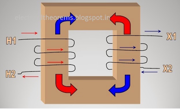
A current transformer is a transformer, which produces in its secondary winding a current, which is proportional to the current flowing in its primary winding. The secondary current is usually smaller in magnitude than the primary current. The principal function of a CT is to produce a proportional current at a level of magnitude, which is suitable for the operation of measuring or protective devices such as indicating or recording instruments and relays. The rated secondary current is commonly 5A or 1A, though lower currents such as 0.5A are not uncommon. It flows in the rated secondary load, usually called the burden, when the rated primary current flows in the primary winding. The primary winding can consist merely of the primary current conductor passing once through an aperture in the current transformer core or it may consist of two or more turns wound on the core together with the secondary winding. These are two basic CT types. The first is commonly called a “ring” type CT as the core is usually annular, but in some cases it may be square or rectangular in shape. The second is usually known as a “wound primary” type CT

WORKING OF CT

The primary and secondary currents are expressed as a ratio such as100/5. With a 100/5 ratio CT, 100A flowing in the primary winding will result in 5A flowing in the secondary winding, provided the correct rated burden is connected to the secondary winding. Similarly, for lesser primary currents, the secondary currents are proportionately lower. It should be noted that a 100/5 CT would not fulfil the function of a 20/1 or a 10/0.5 CT as the ratio expresses the current rating of the CT, not merely the ratio of the primary to the secondary currents.
The extent to which the secondary current magnitude differs from the calculated value expected by virtue of the CT ratio is defined by the [accuracy] “Class” of the CT. The greater the number used to define the class, the greater the permissible “current error” [the deviation in the secondary current from the calculated value]. Except for the least accurate classes, the accuracy class also defines the permissible phase angle displacement between primary and secondary currents. This latter point is important with measuring instruments influenced both by magnitude of current and by the phase angle difference between the supply voltage and the load current, such as kWh meters, wattmeter’s, var meters and power factor meters.


BURDEN RATING
Common burden ratings are 2.5, 5, 10, 15 and 30VA. Currenttransformers are usually either “measuring” or “protective” types, these descriptions being indicative of their functions. The principal requirements of a measuring CT are that, for primary currents up to 120% or125% of the rated current, its secondary current is proportional to its primary current to a degree of accuracy as defined by its “Class” and, in the case of the more accurate types, that a specified maximum phase angle displacement is not exceeded.
A desirable characteristic of a measuring CT is that it should “saturate” when the primary current exceeds the percentage of rated current specified as the upper limit to which the accuracy provisions apply. This means that at these higher levels of primary current the secondary current is les than proportionate. The effect of this is to reduce the extent to which any measuring device connected to the CT secondary is subjected to current overload.
On the other hand the reverse is required of the protective type CT, the principal purpose of which is to provide a secondary current proportional to the primary current when it is several, or many, times the rated primary current. The measure of this characteristic is known as the “Accuracy Limit Factor” (A.L.F.). A protection type CT with an A.L.F. of 10 will produce a proportional current in the secondary winding [subject to the allowable current error] with primary currents up to a maximum of 10 times the rated current.
Preferred primary and secondary current ratings [and therefore ratios], classes, burdens and accuracy limit factors are defined in BS3938 and other comparable national standards, together with other minimum performance requirements, physical construction requirements, etc.
It should be remembered when using a CT that where there are two or more devices to be operated by the secondary winding, they must be connected in series across the winding. This is exactly the opposite of the method used to connect two or more loads to be supplied by a voltage or power transformer where the devices are paralleled across the secondary winding.
With a CT, an increase in the burden will result in an increase in the CT secondary output voltage. This is automatic and necessary to maintain the current to the correct magnitude. Conversely, a reduction in the burden will result in a reduction in the CT secondary output voltage.
This rise in secondary voltage output with an increase in burden means that, theoretically, with infinite burden as is the case with the secondary load open circuit, an infinitely high voltage appears across the secondary terminals. For practical reasons this voltage is not infinitely high, but can be high enough to cause a breakdown in the insulation between primary and secondary windings or between either or both windings and the core. For this reason, primary current should never be allowed to flow with no load or with a high resistance load connected across the secondary winding.

CTs should be specified as follows:

RATIO: input / output current ratio

VA: total burden including pilot wires.

CLASS: Accuracy required for operation

DIMENSIONS: maximum & minimum limits

Metering CTs

In general, the following applies:

CLASS
• 0.1 or 0.2 for precision measurements
• 0.5 for high grade kilowatt hour meters for commercial grade kilowatt hour meters
• 3 for general industrial measurements
• 3 or 5 for approximate measurements

Protection CTs

In addition to the general specification required for CT design, protection CT’s require an Accuracy Limit Factor (ALF). This is the multiple of rated current up to which the CT will operate while complying with the accuracy class requirements.

In general the following applies:

• Instantaneous overcurrent relays & trip coils - 2.5VA Class 10P5
• Thermal inverse time relays - 7.5VA Class 10P10
• Low consumption Relay - 2.5VA Class 10P10
• Inverse definite min. time relays (IDMT) overcurrent - 15VA Class10P10/15
• IDMT Earth fault relays with approximate time grading - 15VA Class10P10
• IDMT Earth fault relays with phase fault stability or accurate time grading required - 15VA Class 5P10

Wednesday, 12 November 2014

itemprop='blogPost' itemscope='itemscope' itemtype='http://schema.org/BlogPosting'>

STAR DELTA STARTER

electrical theory and electrical fundementals for all electrical related people . students , engineers, electrician #electricaltheorems,electrical,

The star delta starting is a very common type of starter and extensively used, compared to the other types of the starters. This method used reduced supply voltage in starting. of a 3phase induction motor with a star – delta starter. The method achieved low starting current by first connecting the stator winding in star configuration, and then after the motor reaches a certain speed, throw switch changes the winding arrangements from star to delta configuration. By connecting the stator windings, first in star and then in delta, the line current drawn by the motor at starting is reduced to one-third as compared to starting current with the windings connected in delta. At the time of starting when the stator windings are start connected


Working Principal of Star-Delta Starter:
This is the reduced voltage starting method. Voltage reduction during star-delta starting is achieved by physically reconfiguring the motor windings as illustrated in the figure below. During starting the motor windings are connected in star configuration and this reduces the voltage across each winding 3. This also reduces the torque by a factor of three. After a period of time the winding are reconfigured as delta and the motor runs normally.
Star/Delta starters are probably the most common reduced voltage starters. They are used in an attempt to reduce the start current applied to the motor during start as a means of reducing the disturbances and interference on the electrical supply.
Traditionally in many supply regions, there has been a requirement to fit a reduced voltage starter on all motors greater than 5HP (4KW). The Star/Delta (or Wye/Delta) starter is one of the lowest cost electromechanical reduced voltage starters that can be applied.
The Star/Delta starter is manufactured from three contactors, a timer and a thermal overload. The contactors are smaller than the single contactor used in a Direct on Line starter as they are controlling winding currents only. The currents through the winding are 1/root 3 (58%) of the current in the line.
There are two contactors that are close during run, often referred to as the main contractor and the delta contactor. These are AC3 rated at 58% of the current rating of the motor. The third contactor is the star contactor and that only carries star current while the motor is connected in star. The current in star is one third of the current in delta, so this contactor can be AC3 rated at one third (33%) of the motor rating

Control Circuit of Star-Delta Starter

The ON push button starts the circuit by initially energizing Star Contactor Coil (KM1) of star circuit and Timer Coil (KT) circuit.
When Star Contactor Coil (KM1) energized, Star Main and Auxiliary contactor change its position from NO to NC.
When Star Auxiliary Contactor (1)( which is placed on Main Contactor coil circuit )became NO to NC it’s complete The Circuit of Main contactor Coil (KM3) so Main Contactor Coil energized and Main Contactor’s  Main and Auxiliary Contactor Change its Position from NO To NC. This sequence happens in a friction of time.
After pushing the ON push button switch, the auxiliary contact of the main contactor coil (2) which is connected in parallel across the ON push button will become NO to NC, thereby providing a latch to hold the main contactor coil activated which eventually maintains the control circuit active even after releasing the ON push button switch.
When Star Main Contactor (KM1) close its connect Motor connects on STAR and it’s connected in STAR until Time Delay Auxiliary contact KT (3) become NC to NO.
Once the time delay is reached its specified Time, the timer’s auxiliary contacts (KT)(3) in Star Coil circuit will change its position from NC to NO and at the Same Time  Auxiliary contactor (KT) in Delta Coil Circuit(4) change its Position from NO To NC so Delta coil energized and  Delta Main Contactor becomes NO To NC. Now Motor terminal connection change from star to delta connection.
A normally close auxiliary contact from both star and delta contactors (5&6)are also placed opposite of both star and delta contactor coils, these interlock contacts serves as safety switches to prevent simultaneous activation of both star and delta contactor coils, so that one cannot be activated without the other deactivated first. Thus, the delta contactor coil cannot be active when the star contactor coil is active, and similarly, the star contactor coil cannot also be active while the delta contactor coil is active.
The control circuit above also provides two interrupting contacts to shutdown the motor. The OFF push button switch break the control circuit and the motor when necessary. The thermal overload contact is a protective device which automatically opens the STOP Control circuit in case when motor overload current is detected by the thermal overload relay, this is to prevent burning of the motor in case of excessive load beyond the rated capacity of the motor is detected by the thermal overload relay.
At some point during starting it is necessary to change from a star connected winding to a delta connected winding. Power and control circuits can be arranged to this in one of two ways – open transition or closed transition.

Tuesday, 11 November 2014

itemprop='blogPost' itemscope='itemscope' itemtype='http://schema.org/BlogPosting'>

UNIVERSAL MOTOR

electrical theory and electrical fundementals for all electrical related people . students , engineers, electrician #electricaltheorems,electrical,

Generally, the electric motors are operated either in DC Power or AC Power. But for some specific applications, it is desirable to introduce a motor that operates on either ac or dc supply. The word ‘Universal’ signifies that something which is compatible with versatile inputs. We have build small series motors up to ½ KW rating which operates on single phase ac supply as well as on dc . Such motors are called universal motors . A universal motor is a specifically designed series wound motor, that operates at approximately the same speed and output on either ac or dc voltage. In case of universal motor, the speed of rotation is slightly lesser when operating in AC. Because, the reactance voltage drop is present on ac but not on dc. So, the motor speed is somewhat lower for same load in ac operation than dc . This takes place especially at high loads . Most universal motors are designed to operate at speeds exceeding 3500 rpm . We will explain discuss the construction of this type of motor


The universal motor is basically a series DC motor which is specially designed to operate on AC as well as on DC. A standard DC series motor has very poor characteristics when operated on AC, mainly due to two reasons:

a) The high reactance of both the armature and field windings limits AC current to a much lower value than DC current (for the same line voltage).

b) If solid steel is used for the stator frame, AC flux will produce large eddy currents in the frame with consequent heating. 
To insure satisfactory operation of the universal motor from an AC power source, some modifications are necessary. The reactance of the series field and armature windings must be reduced as much as practicable. The reactance of the series field winding can be somewhat reduced by using fewer turns of heavier wire. However, it would not be practical to eliminate the reactance voltage drop due to the series field since that would also eliminate the magnetic field. The reactance voltage drop due to the armature winding can be practically eliminated by use of a compensating winding. The compensating winding is connected in series with the armature winding (conductive compensation) and arranged such that the ampere-turns of the compensating winding oppose and neutralize the ampere-turns of the armature. To realize this compensation, the compensating winding is displaced by 90 electrical degrees from the field winding. Since the motor used in this experiment us a 4-pole motor, the mechanical displacement is 450. The compensating winding also improves commutation considerably. This is a great adventure since the field of a universal motor commutation considerably. is weakened by lowering the reactance of the series field winding. If the compensating winding is short circuited (inductive compensation), the alternating currents in the armature are induced by transformer action into the shorted compensating winding, thus, effectively cancelling the reactive armature currents.
To reduce losses due to hysteresis and eddy currents, the field structure is laminated. Few universal motors operate at the same speed on AC as on DC. Whether it runs faster on AC or DC is a matter of design. The reactance of the armature winding can be lowered by placing a compensating winding on the stator so that the fluxes oppose or "cancel" each other. This same compensating winding can be connected in series with the armature winding. In this case, the motor is said to be conductively compensated. Under these conditions, the universal motor will have similar operating characteristics whether on AC or DC power

The compensating winding may be simply shorted upon itself, so that it behaves like a short circuited secondary of a transformer (the armature winding acting as the primary). The induced AC current in the compensating winding again opposes or "bucks" the armature current and the motor is said to be inductively compensated. The reactance of the field winding can be kept low by limiting the number of turns
The starting torque of a universal motor is determined by the current that flows through the armature and field windings. Due to the inductive reactance of these windings the AC starting current will always be less than the DC starting current (with equal supply voltages). Consequently, the starting torque on AC power will be lower than the starting torque on DC power.

The compensating winding has the important role of reducing the overall reactance of the motor. However, it also has an equally important part in opposing armature reaction, thereby improving commutation. An uncompensated universal #motor will lose most of its power. Sparking at the brushes will also be markedly worse

Speed control of universal motor

Speed control of universal motor is best obtained by solid-state devices. Since the speed of these motors is not limited by the supply frequency and may be as high as 20,000 rpm , they are most suitable for applications requiring high speeds . The factors that determine the speed for any dc motor are the same as those for ac series or universal motors i.e flux and generated voltage . Generated voltage change is rarely employed in speed control method. Instead line voltage is varied .This has been accomplished by means of tapped resistor , rheostat in series with the line. Another method is by using a tapped field , thereby reducing the flux and hence raising the speed . This can be achieved by any one of the methods that follow : By using field poles wound in various sections with wires of different size and bringing out the tapsfrom each section By using tapped nichrome wires coils wound over a single field pole. In this method torque decreases with increase in speed 

Monday, 10 November 2014

itemprop='blogPost' itemscope='itemscope' itemtype='http://schema.org/BlogPosting'>

STEPPER MOTOR

electrical theory and electrical fundementals for all electrical related people . students , engineers, electrician #electricaltheorems,electrical,

STEPPER MOTOR 
Stepper motors provide a means for precise positioning and speed control without the use of feedback sensors. The basic operation of a stepper motor allows the shaft to move a precise number f degrees each time a pulse of electricity is sent to the motor. Since the shaft of the motor o moves only the number of degrees that it was designed for when each pulse is delivered, you can control the pulses that are sent and control the positioning and speed. The rotor ofthe motor produces torque from the interaction between the magnetic field in the stator and rotor. The strength of the magnetic fields is proportional to the amount of current sent to the stator and the number of turns in the windings


The stepper motor uses the theory of operation for magnets to make the motor shaft turn a precise distance when a pulse of electricity is provided. You learned previously that like poles of a magnet repel and unlike poles attract.  typical cross-sectional view of the rotor and stator of a stepper motor. From this diagram you can see that the stator (stationary winding) has eight poles, and the rotor has six poles(three complete magnets). The rotor will require 24 pulses of electricity to move the 24 steps to make one complete revolution. Another way to say this is that the rotor will move precisely 15° for each pulse of electricity that the motor receives. The number of degrees the rotor will turn when a pulse of electricity is delivered to the motor can be calculated by dividing the number of degrees in one revolution of the shaft(360°) by the number of poles (north and south) in the rotor. In this stepper motor 360° is divided by 24 to get15°.When no power is applied to the motor, the residual magnetism in the rotor magnets will cause the rotor to detent or align one set of its magnetic poles with the magnetic poles of one of the stator magnets. This means that the rotor will have 24 possible detent positions. When the rotor is in a detent position, it will have enough magnetic force to keep the shaft from moving to the next position. This is what makes the rotor feel like it is clicking from one position to the next as you rotate the rotor by hand with no power applied


When power is applied, it is directed to only one of the stator pairs of windings, which will cause that winding pair to become a magnet. One of the coils for the pair will become the North Pole, and the other will become the South Pole. When this occurs, the stator coil that is the North Pole will attract the closest rotor tooth that has the opposite polarity, and the stator coil that is the South Pole will attract the closest rotor tooth that has the opposite polarity. When current is flowing through these poles, the rotor will now have a much stronger attraction to the stator winding, and the increased torque is called holding torque. 

By changing the current flow to the next stator winding, the magnetic field will be changed 45°. The rotor will only move 15° before its magnetic fields will again align with the change in the stator field. The magnetic field in the stator is continually changed as the rotor moves through the 24 steps to move a total of 360°. the position of the rotor changing as the current supplied to the stator changes

 Stepper Motor Switching Sequence
The stepper motor can be operated in three different stepping modes, namely, full-step, half-step, and micro step.
Full-Step
The stepper motor uses a four-step switching sequence, which is called a full-step switching sequence which is already described above.
Half-Step
Another switching sequence for the stepper motor is called an eight-step or half-step sequence.   The main feature of this switching  sequence is that you can double the resolution of the stepper motor by causing the rotor to move half the  distance it does when the full-step switching sequence is used. This means that a 200-step motor, which has a resolution of 1.8°, will have a resolution of 400 steps and 0.9°. The half-step switching sequence requires a special stepper motor controller, but it can be used with a standard hybrid motor. The way the controller gets the  motor to reach the half-step is to energize both phases at the same time with equal current
In this sequence the first step has SW1  is on, and SW2,SW3 and SW4 are off. The sequence for the first step is the same as the full-step sequence. The second step has SW1 and SW2 are on and all of the remaining switches are off. This configuration of switches causes the rotor to move an additional half-step because it is acted upon by two equal magnetic forces and the rotor turns to the equilibrium position which is half a step angle. The third step has SW2 is on, and SW1, SW4 and SW3 are off, which is the same as  step 2 of the full step sequence. The sequence continues for eight steps and then repeats. The main difference between this sequence and the full-step sequence is that the energizing sequence for half step is A A BB BC CC DD  DA.
Micro Step Mode
The full-step and half-step motors tend to be slightly jerky in their operation as the motor moves from step to step. The amount of resolution is also limited by the number of physical poles that the rotor can have. The amount of resolution (number of steps) can be in-creased by manipulating the current that the controller sends to the motor during each step. The current can be adjusted so that it looks similar to a sine  wave.sent to each of the four sets of windings is timed so that there is always a phase difference with each other.The fact that the current to each individual phase increases and decreases like a sine wave and that is always out of time with the other phase will allow the rotor to reach hundreds of intermediate steps. In fact it is possible for the controller to reach as many as 500 micro steps for a full-step sequence, which will provide 100,000 steps for each revolution.